
Tidal turbine design tutorial: blades and rotor with Heliciel
Designing a tidal turbine with Heliciel means starting from a water-capture propeller model, checking its design point, then watching its runaway speed and its cavitation. Here we study the default SeaGen tidal turbine: a rotor 16 m in diameter in a 2.4 m/s current, turning at 18.2 rpm and delivering about 0.78 MW at the shaft. What sets tidal turbines apart is mastering cavitation: we will see how to visualize it. Author: JF Iglesias (Heliciel developer).
In this tutorial:
- Tidal turbine and Kaplan turbine: what is the difference
- Open the SeaGen tidal turbine model
- Design point and blade geometry
- 3D model and shaft power of the tidal turbine
- Operating point, design point and runaway speed
- Cavitation risk of a tidal turbine
1: Tidal turbine and Kaplan turbine: what is the difference
We discuss here the design of a tidal turbine in open water with Heliciel. The tidal turbine differs from the Kaplan-type hydraulic turbine on one point: it is not in a penstock. The study of the Kaplan turbine in a penstock is detailed in the tutorials and pages on hydropower plants.
- For general information on tidal turbines, also read the article tidal turbines and stream turbines.
- Tidal turbines are of the same nature as wind turbines. We therefore advise you to read first the tutorial on building a wind turbine propeller, to master the prerequisite notion of optimum rotation speed and operating point of an energy-capture rotor.
What sets tidal turbines apart is mainly mastering the problems of cavitation. We will therefore see how to manage and visualize the cavitation of our tidal turbine.
2: Open the SeaGen tidal turbine model
To begin, let us open a capture-type propeller model with the File menu: New project (from a model), then "Water turbine (propeller turbine, tidal turbine)".
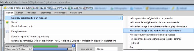
File > New project (from a model): the water-capture propeller line (propeller turbine, tidal turbine) is selected. The capture shows the French menu.
The tidal turbine project proposed by default is a study of a SeaGen tidal turbine 16 m in diameter in a 2.4 m/s current. We use this tidal turbine for our case study:
- rotor diameter: 16 m;
- fluid velocity at the design point: 2.4 m/s.
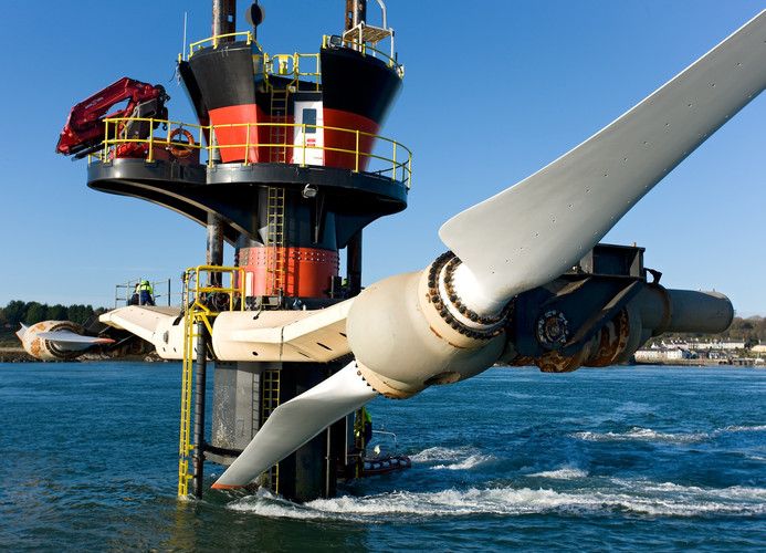
The SeaGen tidal turbine, whose model Heliciel offers by default.
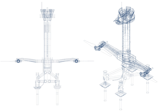
Drawing of the installation: a central mast and a cross-arm that carries two rotors.
3: Design point and blade geometry
The operating point for which the geometry of this model was optimized, the "design point", is visible in tab 1.3 Operating point:
- fluid velocity: 2.4 m/s;
- rotation speed: 18.2 rpm.
The dimensions of the blade are visible in tab 2.1 Blade dimensions:
- the rotor is 16 m in diameter, so the radius at the blade tip is 8,000 mm;
- the radius at the blade root is estimated at 17% of the radius, that is 1,360 mm;
- the chord at the blade root is estimated at 2,000 mm;
- the chord at the blade tip is estimated at 1,000 mm;
- the distribution of the intermediate chords follows the equation Chord = (2.510035E-05) × r² + (−0.3855419) × r + 2,477.912, with r the radius in millimeters.
In tab 2.2 Profiles Law, the constant profile is the naca643418.
4: 3D model and shaft power of the tidal turbine
Let us display the 3D model of this tidal turbine. The video below presents it.
The shaft power is about 0.78 MW. This tidal turbine is rated at 1.2 MW with two rotors. Let us take our model: 0.78 × 2 = 1.56 MW at the shaft. Applying an efficiency of 0.77 for the transmission and the generator, we find the manufacturer data again.
5: Operating point, design point and runaway speed
These two notions must be told apart.
- The operating point is, for a given fluid velocity, the real rotation speed of the tidal turbine. This speed depends on the balance between the torque produced by the rotor and the load torque of the generator and the various parts. If the load torque is smaller than the rotor torque, the propeller turns faster, until its torque equals the load torque. If the load torque is zero (broken gearbox, generator without load…), the rotation speed rises up to the runaway speed, the speed at which the rotor produces a zero or negative torque.
- The design point is the combination of rotation speed and fluid velocity for which the twist of the blades was optimized. Any other rotation speed or fluid velocity produces lower efficiency.
To find the runaway speed with Heliciel, we use the multiple analysis (Optimize tab) and run a multipoint "off design" analysis with the "rotation speed" as the varying parameter. Heliciel then plots the torque and thrust curves as a function of the rotation speed. On this capture, the tested range goes from 10 to 40 rpm in 16 points.
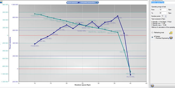
Off-design multiple analysis, varying parameter "rotation speed" from 10 to 40 rpm: the propeller torque (descending curve) falls to zero on the right of the graph, between 36 and 40 rpm.
We see that our tidal turbine has a runaway speed of about 37 rpm, roughly twice its design speed (18.2 rpm), and that at this speed the thrust is about 750,000 N. Let us hope that the engineers took the strength of the support into account for this case.
The off-design multiple analysis varies a parameter that you choose (here the rotation speed) and plots the matching torque and thrust curves. The runaway speed is read where the torque falls to zero.
6: Cavitation risk of a tidal turbine
The pressures displayed in the results area are given for each zone of the blades. They are calculated in three different ways:
- an average pressure, which corresponds to the lift spread over the whole upper surface;
- a concentrated pressure, calculated over the zone between the lift point and the leading edge;
- a drag pressure, calculated from the drag projected on the frontal area of the element.
This lets us distinguish three types of cavitation (see the page on propeller and hydrofoil cavitation). The cavitation threshold is marked by a red line.
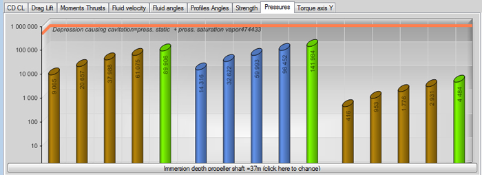
Pressures tab of the results: three series of bars, one per type of pressure, blade element by blade element. The cavitation threshold (static pressure plus saturated vapor pressure, here 474,433 Pa) is the top line, and the immersion depth of the propeller axis (37 m) can be changed by clicking the bottom button. The capture shows the French interface.
Another way to visualize the pressures is to color the blade according to a pressure color code, with the function "Show/Hide the surface pressure for all elements and display in the 3D model".
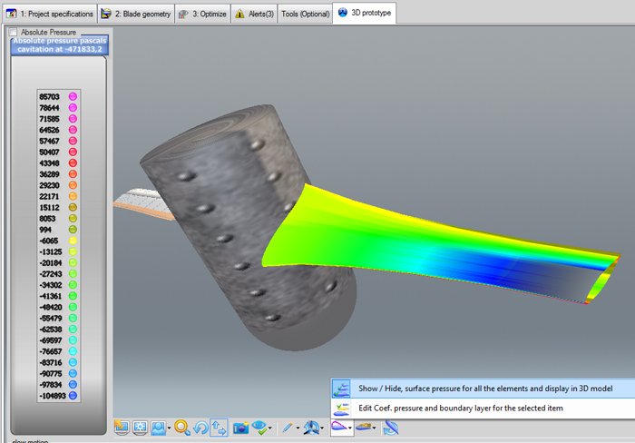
3D prototype: the blade is colored by absolute pressure (color scale on the left, with the cavitation value in its title), and the toolbar menu offers to show or hide this pressure.
To go further, we can go back to the wind turbine propeller tutorial, where the search for the optimum rotation speed is detailed.
That is the end of this short tutorial on the design of tidal turbine rotors with Heliciel. It should put you on the right track to create tidal turbines, or energy recovery devices carried aboard sailing boats, for example.
 Global site map
 Mecaflux
 Tutorials Mecaflux Pro3D
 Tutorials Heliciel
 Tutorials Heliciel PRO CFD
 Mecaflux Store
 Compare software functions
 Quotes, Orders, Payment Methods
 project technical studies